


 English
  Español
  Français
How to Choose a PCBA Manufacturer: Process, Testing & Cost
Content
How to Choose a PCBA Manufacturing Company
The right PCBA manufacturer is the one whose capabilities, quality systems, and volume range actually match your board — not necessarily the one with the lowest quoted price. Evaluating a PCB assembly service provider on process capability first and price second avoids the far more expensive problem of reworking or scrapping a bad production run.
A few factors matter more than most others when narrowing the list:
- Component and package capability: Confirm the manufacturer regularly places the package types your design uses — fine-pitch BGA, QFN, 01005 passives — rather than listing them as a general capability they rarely run.
- Quality certifications: ISO 9001 is a baseline; IPC-A-610 workmanship certification, ISO 13485 for medical devices, or IATF 16949 for automotive indicate the manufacturer is set up for your specific industry's standards.
- Volume flexibility: A manufacturer optimized purely for high-volume runs may be slow and expensive for prototypes, while a prototype-focused shop may not have the line capacity for a jump to mass production.
- Supply chain access and transparency: Ask how the manufacturer sources components, how they handle allocation shortages, and whether they'll flag substitutions before making them rather than after.
- Communication and DFM feedback: A manufacturer that reviews your design for manufacturability and flags issues before production, rather than building exactly what was submitted and letting defects surface later, saves significant rework down the line.
How the PCBA Assembly Process Works
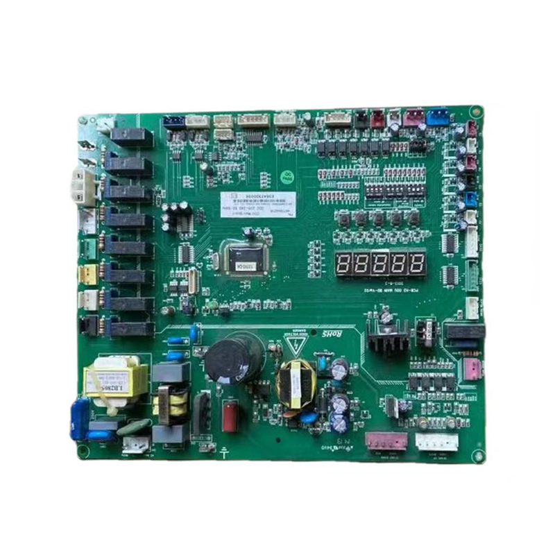
PCBA (printed circuit board assembly) takes a bare fabricated board and populates it with components until it's a functioning electronic assembly. The process follows a consistent sequence regardless of board complexity, though the specific steps used depend on whether components are surface-mount, through-hole, or a mix of both.
- Solder paste application: A stencil matched to the board's pad layout applies solder paste precisely onto each surface-mount pad.
- Component placement: A pick-and-place machine reads the board's fiducial marks and places each surface-mount component onto its paste-coated pad at high speed and precision.
- Reflow soldering: The populated board passes through a reflow oven with a controlled temperature profile that melts the solder paste and forms permanent solder joints as it cools.
- Through-hole insertion and wave or selective soldering: Any through-hole components are inserted, then soldered either by wave soldering (passing the board over a wave of molten solder) or selective soldering for boards where reflow-sensitive components are already in place.
- Inspection and testing: Automated optical inspection, and often X-ray inspection for hidden joints like BGA balls, checks solder quality before the board moves to functional testing.
- Cleaning and conformal coating (if required): Flux residue is cleaned off, and a conformal coating may be applied for boards headed into humid, dusty, or vibration-prone environments.
- Final assembly and packaging: Any mechanical assembly — enclosures, connectors, labels — is completed, followed by final testing and packaging for shipment.
SMT vs. Through-Hole Assembly
Surface-mount technology (SMT) mounts components directly onto pads on the board's surface, while through-hole assembly inserts component leads through drilled holes and solders them on the opposite side. Most modern boards use SMT for the majority of components because it supports far smaller component packages, allows placement on both sides of the board, and is compatible with high-speed automated placement equipment.
Through-hole assembly hasn't disappeared, though — it remains the preferred choice for components that need strong mechanical retention, such as connectors, large capacitors, and transformers that will experience physical stress from cable insertion or vibration. Many production boards combine both: SMT for the bulk of digital and passive components, with through-hole reserved for parts where the added solder joint strength matters more than board space.
What's Included in Turnkey PCBA Assembly
Turnkey PCBA assembly means the manufacturer handles the entire process from bare board fabrication through final tested assembly, rather than the customer supplying pre-purchased components (consignment assembly). A typical turnkey scope includes:
- PCB fabrication to the submitted Gerber files and stackup specification
- Component sourcing and procurement against the bill of materials (BOM)
- Incoming component inspection to verify parts match the BOM before placement
- SMT and through-hole assembly
- Automated optical and/or X-ray inspection
- Functional testing against the customer's test specification
- Packaging and shipping of the finished assembly
The main advantage of turnkey service is a single point of accountability — if a component sourcing issue or assembly defect arises, there's no ambiguity about which party is responsible, which isn't always the case when a customer supplies their own components under a consignment model.
Prototype vs. Mass Production PCBA
Prototype PCBA and mass production PCBA use the same core assembly techniques but differ sharply in priorities, tooling, and lead time. Prototype runs — typically a handful to a few hundred units — prioritize speed and design validation, often using flexible, lower-volume equipment and manual or semi-automated processes to accommodate frequent design revisions between builds.
Mass production shifts the priority to consistency and unit cost. Manufacturers set up dedicated stencils, programmed pick-and-place feeders, and fixed test jigs for the specific design, which lowers per-unit cost significantly but makes design changes mid-run expensive and disruptive. Moving from prototype to mass production typically also triggers a formal design-for-manufacturing (DFM) review, since issues that were manageable at low volume — tight tolerances, hand-placed components, marginal thermal margins — can turn into yield problems at scale.
Common PCBA Testing Methods
PCBA testing methods are layered, with each stage catching different classes of defects that later stages either can't detect or would be far more costly to catch after final assembly.
| Test Method | What It Detects |
|---|---|
| Automated Optical Inspection (AOI) | Missing, misaligned, or wrong-value components; visible solder defects |
| X-ray Inspection (AXI) | Hidden solder joints under BGAs and QFNs, voids, insufficient solder |
| In-Circuit Testing (ICT) | Shorts, opens, and incorrect component values via direct electrical probing |
| Flying Probe Testing | Same faults as ICT, without requiring a dedicated fixture — suited to low volumes |
| Functional Testing (FCT) | Whether the assembled board actually performs its intended function |
| Burn-In Testing | Early-life component failures, by running the board under load over an extended period |
How Much Does PCBA Manufacturing Cost
PCBA manufacturing cost is a combination of the bare board cost, component cost, and assembly labor/machine time, and the weighting between these shifts heavily depending on volume. At prototype quantities, setup and NRE (non-recurring engineering) charges — stencils, programming, fixtures — are spread across very few units, so per-board cost can run several times higher than the same design at production volume.
Component selection tends to be the single largest cost driver at any volume: parts on allocation, single-source components, or exotic packages can dominate the BOM cost regardless of how efficiently the board is assembled. Board complexity — layer count, component density, and the mix of SMT versus through-hole — adds assembly time and machine cost on top of that.
How to Reduce PCBA Manufacturing Costs
Most meaningful cost reduction happens at the design stage, before the board ever reaches the assembly line — retrofitting cost savings onto a finished design is far more limited.
- Standardize on common components: Favoring widely stocked, multi-sourced parts over single-source or exotic components reduces both unit cost and the risk of costly last-minute substitutions.
- Minimize unique part numbers: Reusing the same resistor, capacitor, or connector value across a design instead of introducing a new part number for a marginal improvement reduces both BOM cost and line changeover time.
- Design for single-sided placement where possible: Keeping components on one side of the board avoids a second reflow pass and the added handling that double-sided assembly requires.
- Avoid unnecessarily tight tolerances: Specifying tighter tolerances than the circuit actually needs — on components, drill sizes, or trace width/spacing — drives up fabrication and assembly cost without a functional benefit.
- Order at realistic production volumes: Because NRE and setup costs are largely fixed per run, consolidating orders into fewer, larger production runs (rather than frequent small batches) lowers the effective per-unit cost.
- Get a DFM review before committing to production: Catching a component footprint error or an unsupportable tolerance during design-for-manufacturing review is far cheaper than discovering it after a production run has already started.

 LET'S CREATE THE FUTURE TOGETHER

Contact Us Anytime
Copyright © Anhui Hongxin Electronic Technology Co., Ltd. All Rights
Reserved.
privacy
Wholesale Printed Circuit Board Suppliers, Manufacturers

