The Complete Guide to High Frequency PCBs: Materials, Manufacturing, and Applications
In the era of 5G, autonomous driving, and advanced satellite communications, High Frequency Printed Circuit Boards (PCBs) form the critical hardware backbone for reliable high-speed signal transmission. This guide provides an in-depth exploration of High Frequency PCB technology, from core material science to advanced manufacturing and supply chain considerations, offering valuable insights for design engineers and procurement specialists.
Material Science: The Foundation of High-Frequency Performance
The selection of substrate material is the most critical decision in high-frequency PCB design, as it directly dictates signal integrity.
| Key Material Parameter |
Impact on Performance |
| Dielectric Constant (Dk) |
Determines signal propagation speed and impedance. A stable Dk across frequency and temperature is crucial for consistent performance. |
| Dissipation Factor (Df) |
Measures signal loss in the dielectric material. A lower Df is essential for minimizing attenuation in high-speed and RF applications. |
| Thermal Properties |
Includes Coefficient of Thermal Expansion (CTE) and thermal conductivity. Good thermal management ensures reliability under power. |
Manufacturers like Anhui Hongxin Electronic Technology Co., Ltd. offer a range from standard FR-4 to specialized high-frequency laminates, ceramic, and metal-core substrates, enabling optimal material selection for applications from consumer wireless to automotive radar.
Precision Manufacturing: Enabling Signal Integrity
Translating design into a functional board requires meticulous process control to maintain the electrical properties dictated by the materials.
- Critical Fabrication Tolerances: Achieving fine-line geometries, such as a minimum trace/space of 3 mils (0.075mm), is fundamental. Precise control over dielectric thickness and copper etching is equally vital for consistent impedance matching, often requiring tolerances within ±10%.
- Advanced Construction Capabilities: Modern high-frequency designs often demand complex multi-layer structures (e.g., up to 32 layers), hybrid builds combining different materials, and specialized via technologies like buried and blind vias to manage signal paths in 3D space.
From Prototype to Production: Navigating Lead Times and Quality
Balancing rapid development with volume production reliability is a key challenge in the electronics industry.
- Structured Delivery Cycles: A transparent and reliable production schedule is essential. Capabilities range from ultra-fast 24-hour prototyping for double-sided boards to structured lead times for complex multi-layer batches (e.g., 9-20 days for 4-8 layers, 25-45 days for 16-32 layers), allowing for efficient project planning.
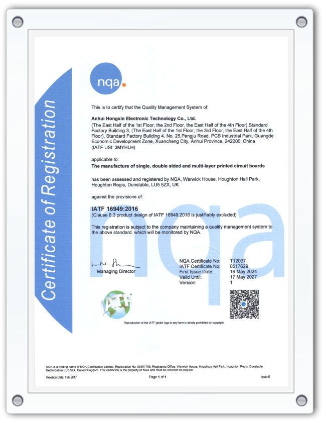
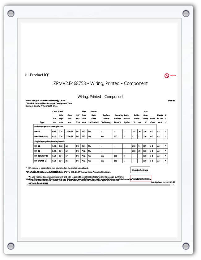
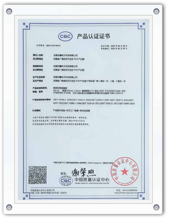
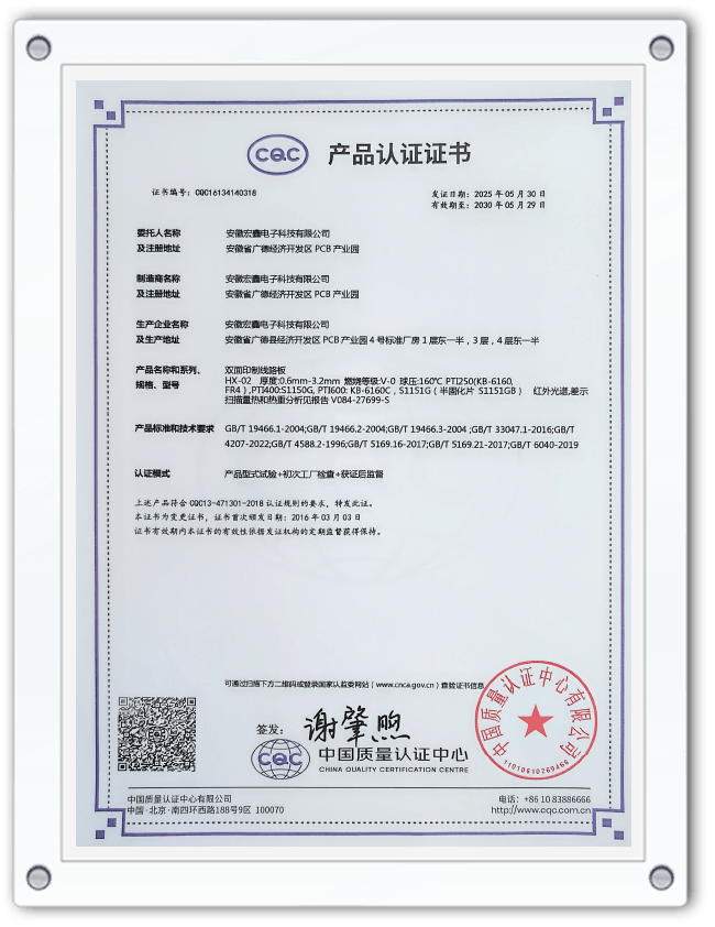
- Comprehensive Quality Assurance: Trust in a PCB supplier is built on verifiable quality systems. Certifications such as ISO9001, IATF16949 (for automotive), and UL listing demonstrate a commitment to rigorous process control, material traceability, and product safety from prototype through mass production.
Application-Specific Solutions: 5G, Automotive Radar, and Satellite Comms
Different cutting-edge applications impose unique demands on high-frequency PCB technology.
- 5G Infrastructure: Base station boards require large formats, excellent thermal management for power amplifiers, and often hybrid constructions using both standard and high-frequency materials within the same stack-up.
- Automotive Radar (e.g., 77GHz): This application demands ultra-low-loss materials, exceptionally consistent dielectric properties for accurate phase response, and adherence to stringent automotive reliability standards (AEC-Q).
- Satellite Communications: Boards must survive extreme thermal cycling in space, often requiring specialized, stable substrates and sometimes metal-core boards for both thermal dissipation and structural rigidity.
FAQ
What is the main difference between a standard FR-4 PCB and a High Frequency PCB?
The core difference lies in the substrate material. Standard FR-4 has a relatively high and inconsistent Dissipation Factor (Df), causing significant signal loss at GHz frequencies. High Frequency PCBs use specialized laminates (like Rogers, Taconic, or PTFE-based materials) with a very low and stable Dk and Df. This minimizes signal attenuation, preserves signal integrity, and allows for precise impedance control, which is non-negotiable for RF and high-speed digital designs.
How do I choose the right high-frequency PCB material for my application?
Material selection is a trade-off between electrical performance, mechanical properties, cost, and manufacturability. Start by defining your key parameters:
- Operating Frequency: Higher frequencies require materials with lower Df.
- Loss Tolerance: How much signal loss can your system afford?
- Thermal & Environmental Needs: Consider power dissipation, operating temperature range, and humidity.
- Budget: Specialized high-frequency materials are more expensive than FR-4.
Consulting with an experienced manufacturer's engineering team early in the design phase is highly recommended to navigate these choices effectively.
Why is impedance control so critical in High Frequency PCB design, and how is it achieved?
Impedance control ensures that signals travel without reflection, which causes distortion and data errors. At high frequencies, traces act as transmission lines. Their impedance (typically 50 or 100 ohms) depends on the trace width, thickness, the dielectric constant (Dk) of the substrate, and the distance to the reference plane. It is achieved through precise manufacturing:
- Using materials with a tight-tolerance, stable Dk.
- Fabricating traces with exacting width and thickness control.
- Maintaining consistent dielectric layer heights.
A capable manufacturer will have the process expertise to deliver boards with impedance tolerances within ±10% or better.
What certifications should I look for when selecting a High Frequency PCB manufacturer?
Key certifications indicate a robust quality management system:
- IATF 16949: The automotive quality standard, essential for automotive radar and ADAS applications, demonstrating advanced process control and traceability.
- ISO 9001: The baseline for quality management systems.
- UL Recognition: Ensures the materials and board meet safety standards, often a requirement for end-product certification.
- Additional ISO standards (14001, 45001): Indicate responsible environmental and safety practices.
A manufacturer holding these certifications, like Anhui Hongxin Electronic Technology Co., Ltd., provides greater assurance of consistent quality and reliability.
What are the key advantages of partnering with a manufacturer that offers both rapid prototyping and volume production?
This integrated approach offers significant strategic benefits:
- Design Continuity: The knowledge gained during the prototyping phase (regarding material behavior, manufacturability, and testing) is seamlessly transferred to volume production, reducing risk and delays.
- Supply Chain Simplification: Working with a single partner for both stages streamlines communication, ensures consistency, and reduces administrative overhead.
- Speed to Market: Fast prototyping accelerates design validation, while guaranteed production capacity ensures you can scale up quickly once the design is finalized.
This end-to-end capability is crucial for thriving in fast-paced technology sectors like telecommunications and automotive electronics.


 English
  Español
  Français