Engineering for Efficiency: The Comprehensive Guide to High Power PCB Technology
In the realm of modern electronics, managing significant electrical energy efficiently and reliably is paramount. The High Power PCB is the engineered foundation for such applications, from LED lighting and power supplies to electric vehicle inverters and industrial motor controls. Unlike standard circuit boards, these specialized PCBs are designed to handle high currents, dissipate substantial heat, and operate reliably under demanding electrical and thermal stress. This guide delves into the critical design considerations, material science, and manufacturing processes that define high-performance power electronics.
Thermal Management: The Core of High Power PCB Design
The primary challenge in any high-power application is heat. Excessive heat degrades components, reduces lifespan, and can cause catastrophic failure. Therefore, effective thermal management is not just a feature but a necessity.
Key Thermal Design Parameters
- Copper Thickness: Measured in ounces per square foot (oz/ft²), thicker copper traces carry more current with less resistive heating. Standard boards use 1oz (35µm), while high-power boards commonly use 3oz (105µm) to 12oz (420µm) or more.
- Thermal Conductivity of Substrate: The material's ability to conduct heat away from components. Standard FR-4 has low thermal conductivity (~0.3-0.4 W/mK), while metal-core boards are far superior.
- Thermal Via Arrays: Plated-through-holes placed under hot components to transfer heat from the surface layer to inner layers or a dedicated heat sink.
| Substrate Type |
Typical Thermal Conductivity (W/mK) |
Best Use Case |
| Standard FR-4 |
0.3 - 0.4 |
Low-to-medium power, cost-sensitive applications. |
| Aluminum Core (MCPCB) |
1.0 - 2.5 |
High-power LEDs, automotive lighting, power supplies. |
| Copper Core |
380 - 400 |
Extremely high-power or high-density applications where heat must be spread quickly. |
| Ceramic Substrate (AlN, Al2O3) |
20 - 200 |
High-frequency RF power amplifiers, aerospace, and high-reliability applications. |
Material Selection and Electrical Considerations
Beyond thermal properties, the choice of materials and design dictates the electrical performance and long-term reliability of the board.
- Current Carrying Capacity: Determined by copper thickness, trace width, and the allowable temperature rise. Engineers use IPC-2152 charts to calculate the required cross-sectional area for a given current.
- Dielectric Strength: The ability of the insulating layers to withstand high voltages without breakdown. This is critical in power converters and inverters.
- Material Stability: High-Tg (Glass Transition Temperature) materials are essential to prevent the board from warping or delaminating during soldering and high-temperature operation. A Tg of 170°C or higher is common for demanding applications.
Manufacturers like Anhui Hongxin Electronic Technology Co., Ltd. offer a wide range of materials, including high-Tg FR-4, metal substrates, and specialized laminates, allowing engineers to select the optimal balance of thermal, electrical, and mechanical properties for their specific design.
Manufacturing Excellence and Quality Assurance
Producing a reliable High Power PCB requires advanced manufacturing capabilities and a rigorous quality control system. The process involves precise control of lamination pressures, copper plating thickness, and drilling accuracy to create robust thermal vias and multi-layer structures.
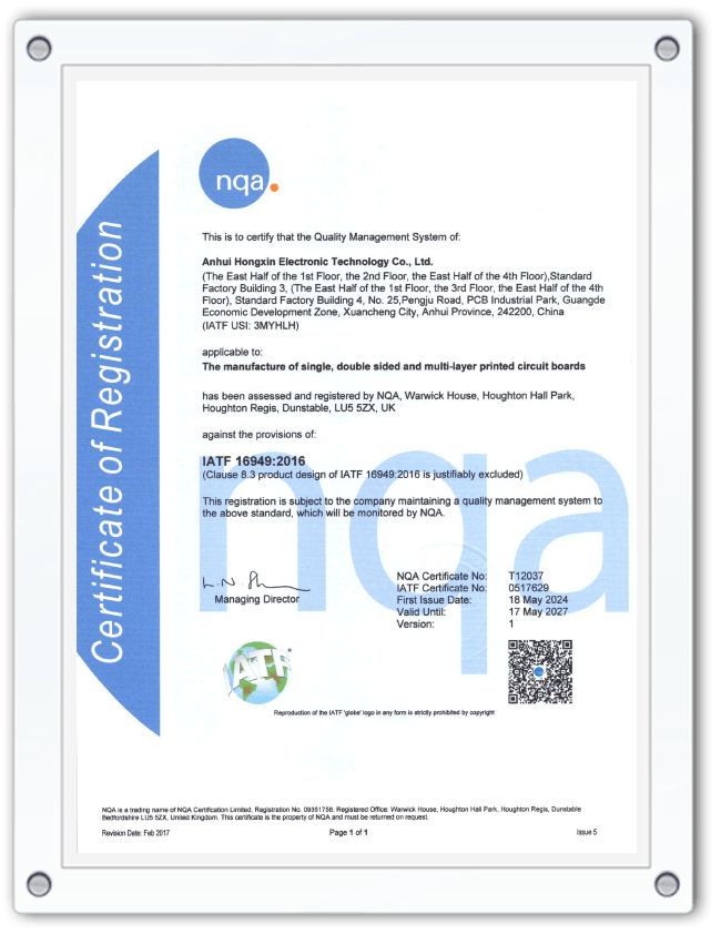
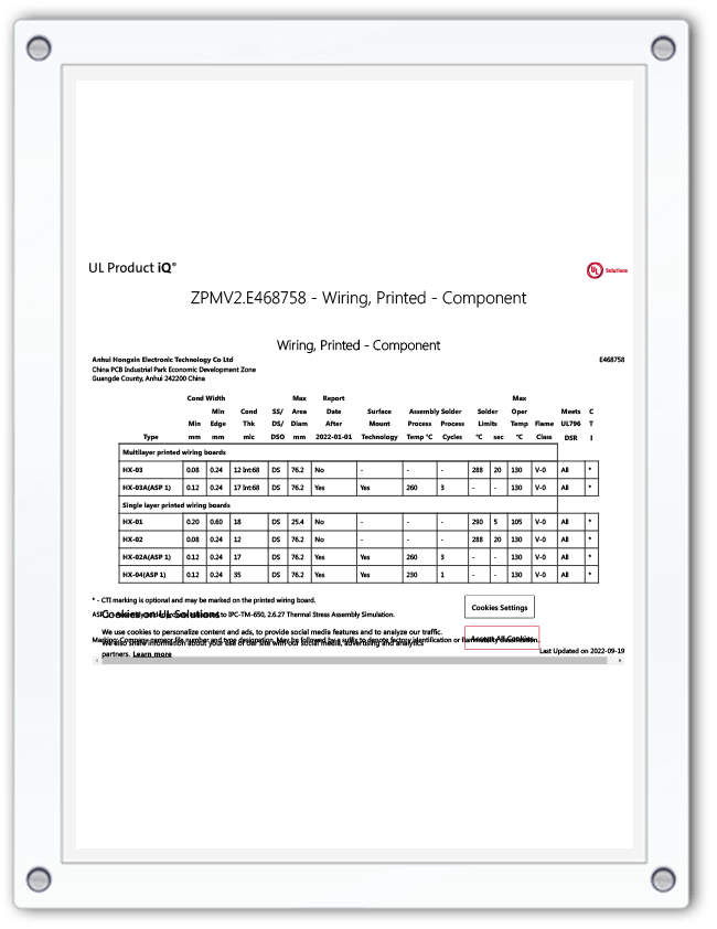
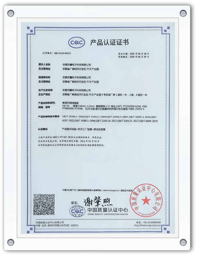
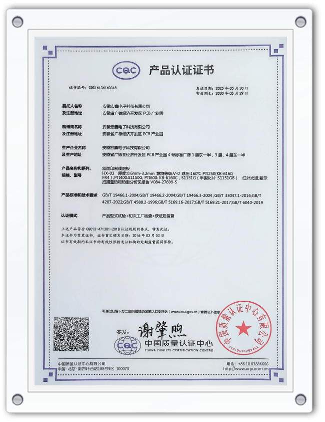
For mission-critical applications, such as those in the automotive industry, adherence to international standards is non-negotiable. Certifications like IATF 16949 demonstrate a manufacturer's commitment to quality, consistency, and continuous improvement. Furthermore, UL certification ensures the product meets strict safety and flammability standards. Anhui Hongxin Electronic Technology Co., Ltd.'s portfolio of certifications, including ISO9001, ISO14001, ISO45001, IATF16949, and UL, underscores its capability to deliver high-reliability High Power PCBs to a global customer base.
FAQ
What is the main difference between a standard PCB and a High Power PCB?
The main difference lies in their design focus and material composition. A standard PCB is optimized for signal integrity in low-current applications. A High Power PCB is engineered to manage two primary challenges: high current and significant heat generation. This is achieved through:
- Thicker Copper: Using 3oz, 6oz, or even thicker copper to reduce resistance and handle high currents without overheating.
- Thermally Conductive Substrates: Employing metal-core (aluminum or copper) or other specialized materials to act as a built-in heat sink.
- Robust Construction: Designs that incorporate features like thermal vias and larger pad sizes to enhance heat dissipation and component soldering reliability.
Essentially, a High Power PCB is a purpose-built thermal and electrical management platform.
When should I choose an aluminum core PCB over a standard FR-4 PCB?
You should choose an aluminum core PCB (MCPCB) when your design involves components that generate a significant amount of heat that needs to be efficiently conducted away. Key indicators include:
- High-Power LEDs: This is the most common application. MCPCBs are essential for maintaining LED junction temperature, which directly affects their brightness, color consistency, and lifespan.
- Power Conversion Circuits: For switching regulators, motor drivers, and power supplies where components like MOSFETs and inductors dissipate considerable heat.
- Space-Constrained Designs: When you cannot fit a large heat sink, an MCPCB integrates the heat-spreading function directly into the board, saving space and simplifying assembly.
If your application is purely for logic or low-power signal processing, a standard FR-4 board is more cost-effective. The choice is dictated by the thermal budget of your design.
How does copper thickness affect the performance of a High Power PCB?
Copper thickness is a critical parameter that directly impacts a High Power PCB's performance in two key ways: current carrying capacity and heat dissipation.
- Current Carrying Capacity: A wider and thicker copper trace has lower electrical resistance. According to Ohm's Law (P = I²R), lower resistance means less power is lost as heat for a given current. Thicker copper allows you to safely conduct higher currents without exceeding the board's temperature limits. For example, a 6oz trace can carry significantly more current than a 1oz trace of the same width.
- Heat Spreading: Copper is an excellent conductor of heat. A thick copper layer acts as a heat spreader, distributing heat from a hot component (like a power IC) over a larger area of the PCB. This reduces the "hot spot" temperature and makes the entire board more efficient at transferring heat to the ambient environment or a heat sink.
Choosing the correct copper thickness is a fundamental trade-off between performance, cost, and manufacturing complexity.
What design features are crucial for ensuring the long-term reliability of a High Power PCB?
Ensuring long-term reliability in a High Power PCB requires proactive design to mitigate the stresses of high current and heat cycling. Crucial features include:
- Thermal Relief Pads: For through-hole components connected to large copper planes (like ground or power), thermal relief connections are used. They reduce the direct heat sink effect during soldering, ensuring a good solder joint, while still providing a good electrical and thermal connection during operation.
- Adequate Via Sizing and Plating: Thermal vias must be large enough and have sufficient copper plating thickness to effectively transfer heat. For high-reliability applications, via filling and capping with solder or epoxy can prevent moisture ingress and improve thermal transfer.
- Conformal Coating: Applying a protective chemical coating can protect the board from moisture, dust, and chemical contaminants, which is especially important in harsh industrial or automotive environments.
- Material Selection: Using materials with a high Tg and low Coefficient of Thermal Expansion (CTE) reduces the mechanical stress on vias and components during temperature fluctuations, preventing cracks and delamination over time.
These features, combined with manufacturing under a quality system like IATF 16949, are essential for creating a High Power PCB that will last for years in the field.


 English
  Español
  Français