Conquering the Millimeter Wave: A Deep Dive into High-Speed PCB Technology
The performance of modern electronics, from 5G base stations to advanced driver-assistance systems, hinges on a critical component: the High-Speed PCB. As signal frequencies climb into the multi-gigahertz and millimeter-wave ranges, the physical properties of the printed circuit board become a primary factor in system success. This article explores the core technologies, material science, and manufacturing precision required to master high-speed PCB design and production, drawing on the capabilities of leading manufacturers like Anhui Hongxin Electronic Technology Co., Ltd.
Material Science: The Foundation of Signal Integrity
At frequencies above 10GHz, traditional FR-4 materials often fall short due to higher signal loss and unstable dielectric properties. Selecting the right substrate is the first and most crucial step.
| Parameter |
Standard FR-4 |
High-Frequency Material |
Impact on Performance |
| Dielectric Constant (Dk) |
4.5 - 5.0 |
3.0 - 4.5 |
Lower Dk enables faster signal propagation and reduces signal delay. |
| Dissipation Factor (Df) |
0.015 - 0.025 |
0.002 - 0.004 |
Lower Df significantly reduces signal attenuation (loss), crucial for long traces. |
| Glass Transition Temperature (Tg) |
130°C - 140°C |
> 170°C (High-Tg) |
Higher Tg ensures the board remains dimensionally stable during soldering and high-temperature operation. |
For applications demanding the utmost performance, hybrid dielectric laminated boards offer an optimal solution. These boards strategically combine high-frequency materials in critical signal layers with more cost-effective FR-4 in power or ground layers, balancing performance with manufacturing cost.
The Art of Impedance Control
In high-speed design, controlling the impedance of signal traces is non-negotiable. Mismatched impedance leads to signal reflections, causing data corruption and system failure. Achieving precise impedance control requires tight manufacturing tolerances.
- Target Impedance: Common single-ended impedance is 50Ω, while differential pairs are often 90Ω or 100Ω.
- Impedance Tolerance: A standard tolerance is ±10%. For high-performance applications, a tighter tolerance of ±7% or even ±5% is required.
- Key Factors: The final impedance is a function of trace width, trace height, dielectric thickness, and the material's Dk. Manufacturers must precisely control each of these variables.
Companies like Anhui Hongxin Electronic Technology Co., Ltd., with their team of experienced engineers, utilize advanced simulation tools and tightly controlled processes to ensure that every manufactured board meets the specified impedance profile across all layers.
Agile Manufacturing: From Prototype to Production
The speed of innovation demands an equally agile manufacturing response. The ability to rapidly prototype and then scale to mass production is a key competitive advantage.
Typical Production Lead Times:
- Double-sided Prototyping: As fast as 24 hours.
- 4-8 Layer Boards (Volume): 9-20 days.
- 10-16 Layer Boards (Volume): 20-25 days.
- HDI Boards (Volume): Within 25 days.
This agility is supported by a comprehensive manufacturing footprint, including a 20,000 square meter factory and a complete suite of surface treatment processes, allowing for both small-batch rapid prototyping and large-volume production without sacrificing quality.
Reliability and Certification: Meeting Industry Standards
For high-stakes applications in automotive and industrial sectors, a High-Speed PCB must be more than just electrically sound; it must be exceptionally reliable and certified to stringent international standards.
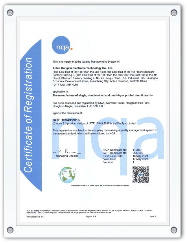
- IATF 16949: This certification is the gold standard for the automotive industry, demonstrating a commitment to quality management, defect prevention, and continuous improvement.
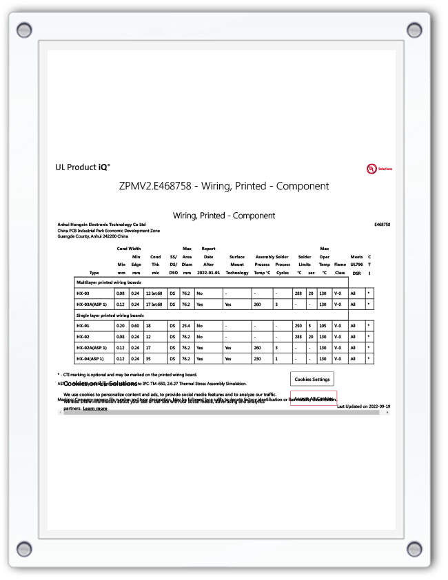
- UL Certification: Ensures the product meets safety and flammability standards, such as the UL 94V-0 rating for flame retardancy.
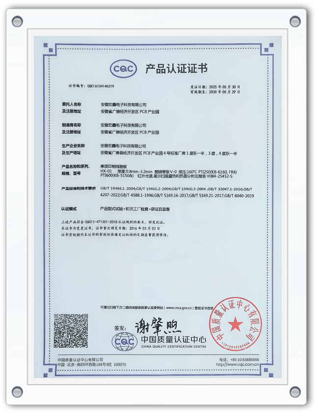
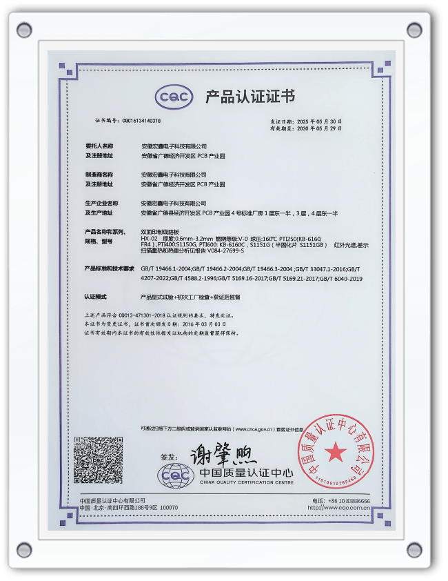
- Material Compliance: Utilizing High-Tg and halogen-free materials addresses both high-temperature reliability and environmental regulations.
A manufacturer's portfolio of certifications, including ISO9001, ISO14001, and IATF16949, is a clear indicator of its capability to deliver reliable, high-quality High-Speed PCBs for global markets.
FAQ
What is the difference between a standard PCB and a High-Speed PCB?
The primary difference lies in material selection and manufacturing precision. A standard PCB, often made from FR-4, is designed for lower-frequency applications where signal loss and dielectric stability are less critical. A High-Speed PCB uses specialized laminates with a lower and more stable dielectric constant (Dk) and a much lower dissipation factor (Df) to minimize signal loss at high frequencies. Furthermore, High-Speed PCBs require much tighter manufacturing tolerances for impedance control, trace geometry, and layer registration to ensure signal integrity. They are essential for applications like 5G, high-speed computing, and advanced radar systems.
Why is impedance control so critical in High-Speed PCB design?
Impedance control is critical because it ensures that the impedance of the PCB trace matches the impedance of the source (e.g., a transmitter chip) and the load (e.g., a receiver chip). When there is an impedance mismatch, a portion of the signal is reflected back to the source instead of being transmitted to the receiver. These reflections cause signal distortion, ringing, and data errors, which can lead to complete system failure. In high-speed digital and high-frequency analog circuits, even small reflections can be destructive, making precise impedance control (e.g., 100Ω ±10% for a differential pair) a fundamental requirement for a functional product.
When should I use Rogers material instead of FR-4 for my PCB?
You should consider using Rogers material instead of FR-4 when your application involves operating frequencies typically above 2-5GHz, where signal loss becomes a significant problem. Key indicators for needing Rogers or other high-frequency laminates include:
- High Frequency: Applications like 5G (mmWave), automotive radar (77GHz), and high-speed serdes (above 10 Gbps).
- Stringent Signal Integrity Requirements: When your design requires minimal signal attenuation and low distortion over long trace lengths.
- Tight Tolerance on Dk: Rogers materials offer a much tighter tolerance on dielectric constant, which is essential for predictable impedance and performance in complex RF and microwave circuits.
While FR-4 is more cost-effective, for any high-frequency, performance-critical application, investing in Rogers material is necessary to ensure the product will function as designed.
What are the key considerations for choosing a surface finish for a High-Speed PCB?
The choice of surface finish for a High-Speed PCB impacts solderability, shelf life, reliability, and even high-frequency performance. Key considerations include:
- ENIG (Electroless Nickel Immersion Gold): Offers a flat, planar surface suitable for fine-pitch components and provides a long shelf life. However, the nickel layer can be a bit "harder" for soldering and can introduce signal loss at very high frequencies.
- ENEPIG (Electroless Nickel Electroless Palladium Immersion Gold): Considered a premium finish. The palladium barrier prevents nickel migration and provides a highly reliable, solderable surface with excellent high-frequency performance, making it ideal for demanding applications.
- OSP (Organic Solderability Preservative): A cost-effective, flat surface that is very friendly to soldering. However, it has a limited shelf life (typically 6-12 months) and is not suitable for applications requiring multiple reflow cycles or wire bonding.
For most High-Speed PCB applications, ENIG is a common and reliable choice, while ENEPIG is selected for the most critical, high-reliability, and very high-frequency designs.


 English
  Español
  Français