

 English
  Español
  Français
FR4 PCB Material: Properties, Dielectric Constant, CTE & Datasheet Guide
Content
- 1 What Is FR4? Definition and Industry Standing
- 2 FR4 Material Properties: The Complete Technical Profile
- 3 What Is PCB Layout and How FR4 Properties Affect Design Decisions
- 4 FR4 Variants: Standard, High-Tg, Halogen-Free, and FR1 Comparison
- 5 When FR4 Is Not the Right PCB Material
- 6 Reading an FR4 Material Data Sheet: What to Check
What Is FR4? Definition and Industry Standing
FR4 — also written FR-4 — is the most widely used base material for printed circuit boards worldwide. The designation stands for Flame Retardant Type 4, a grade classification defined by the National Electrical Manufacturers Association (NEMA) under the LI 1 standard. It specifies a woven fiberglass cloth reinforcement embedded in an epoxy resin matrix, with a bromine-based or phosphorus-based flame retardant system incorporated into the resin to meet UL 94 V-0 flammability requirements.
FR4 has been the dominant PCB material since the 1970s, displacing earlier phenolic paper laminates (FR1, FR2) and cotton-glass composites (FR3) across virtually all mainstream electronics applications. Its combination of electrical insulation performance, mechanical strength, dimensional stability, moisture resistance, and processability at competitive cost remains unmatched by any single alternative material at comparable price points. An estimated 90% or more of all rigid PCB circuit boards produced globally use FR4 or a derivative formulation as the substrate.
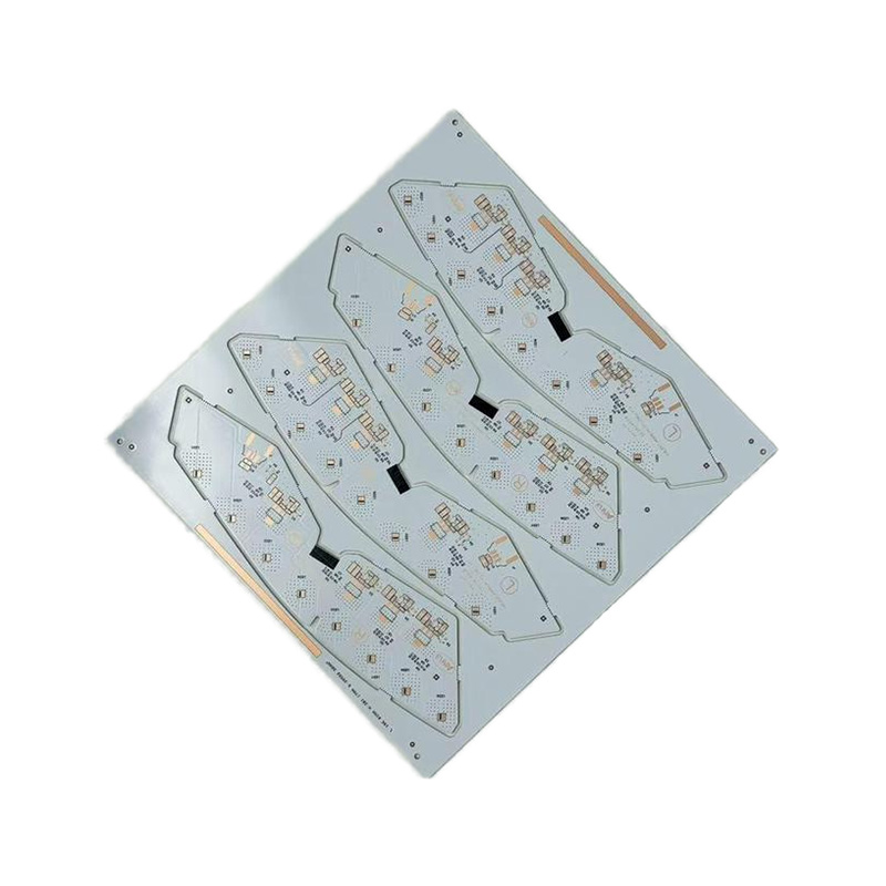
The term "FR4" technically refers to the laminate material — the dielectric base — rather than the finished board. An FR4 PCB board or FR4 printed circuit board is a completed board in which the substrate is FR4 laminate, copper foil layers are bonded to one or both surfaces, and conductive traces, pads, and vias are formed through etching and drilling processes.
FR4 Material Properties: The Complete Technical Profile
FR4 material properties vary to a degree between manufacturers and specific formulations, but the values below represent the established standard range for general-purpose FR4 laminate as specified in IPC-4101 slash sheets /21 and /24 (the most common commercial grades). Design engineers referencing an FR4 material datasheet should treat manufacturer-specific values as authoritative for any given product, but the figures below are reliable for preliminary design calculations.
Dielectric Properties
The dielectric constant of FR4 — also called relative permittivity (Dk or εr) — is one of the most referenced parameters in PCB design. It determines signal propagation velocity and the impedance of controlled-impedance traces. Standard FR4 has a dielectric constant of approximately 4.2–4.6 measured at 1 MHz, commonly cited as 4.3 or 4.4 for design reference. At higher frequencies (1 GHz), the relative dielectric constant of FR4 typically drops to the 4.0–4.2 range due to frequency dispersion in the epoxy-glass composite.
This frequency dependence is a critical limitation of standard FR4 in high-speed digital and RF design. Above approximately 1–2 GHz, the variation in relative permittivity of FR4 with frequency becomes significant enough to cause signal integrity problems — propagation delay variation, differential pair skew, and impedance deviation from nominal. Low-loss FR4 variants and purpose-designed high-frequency laminates (Rogers, Isola, Taconic) address this at higher cost.
The dissipation factor (Df, loss tangent) of standard FR4 is 0.017–0.025 at 1 MHz, rising with frequency. For comparison, Rogers RO4003C has a Df of 0.0027 — roughly an order of magnitude lower — which is why standard FR4 dielectric material is not used in microwave or millimeter-wave applications.
Mechanical Properties
FR4 is a hard, rigid laminate with good flexural strength:
- Flexural strength (lengthwise): 415–550 MPa
- Tensile strength: 310–410 MPa (lengthwise)
- Young's modulus (in-plane): approximately 18–24 GPa
- Compressive strength: 415 MPa (perpendicular to laminate)
- Rockwell hardness (M scale): 110
These values make FR4 substantially stronger than thermoplastic PCB substrates and sufficiently rigid for automated PCB assembly processes including pick-and-place, wave soldering, and reflow without requiring fixture support for standard board thicknesses (1.0–3.2 mm).
Thermal Properties
Thermal performance is the most commonly cited limitation of FR4 in power electronics and high-dissipation applications:
- Thermal conductivity of FR4: 0.25–0.35 W/(m·K) in-plane; approximately 0.3 W/(m·K) perpendicular to the laminate. This is very low compared to aluminum (205 W/(m·K)) or copper (385 W/(m·K)), which is why thermal vias, copper pours, and metal-core PCB substrates are used in thermally demanding designs.
- Glass transition temperature (Tg): Standard FR4 — 130–140°C; mid-Tg FR4 — 150–160°C; high-Tg FR4 — 170–180°C. Above Tg, the epoxy matrix softens and the material loses dimensional stability. Lead-free soldering processes peak at 260°C, which is why high-Tg FR4 is specified for RoHS-compliant assemblies.
- Decomposition temperature (Td): 300–340°C for standard grades; above 340°C for high-reliability halogen-free formulations.
- Specific heat capacity: approximately 1.0–1.1 J/(g·K)
Coefficient of Thermal Expansion (CTE of FR4)
The CTE of FR4 is anisotropic — it differs significantly between in-plane (x-y) and out-of-plane (z-axis) directions:
- CTE x-y (in-plane): 14–17 ppm/°C (below Tg)
- CTE z-axis (through-thickness): 50–70 ppm/°C (below Tg); 200–300 ppm/°C above Tg
The high z-axis CTE is the principal cause of barrel cracking in plated through-holes (PTH) during thermal cycling. The z-axis expansion stresses the copper barrel of the via, which has a CTE of only 17 ppm/°C, creating fatigue cracks at the knee radius after repeated thermal excursions. This is a design-life concern in high-cycle environments such as automotive and industrial electronics, and it drives the specification of high-Tg or halogen-free FR4 variants with lower z-axis CTE.
Physical Properties
- FR4 material density: 1.85–1.95 g/cm³ (typically cited as 1.9 g/cm³ for standard glass-epoxy FR4). The density of FR4 material is primarily determined by the glass fiber volume fraction and the resin system. Higher glass content increases density; halogen-free resins with different filler loadings can shift density slightly.
- Water absorption (24h immersion): 0.10–0.20% by weight — low enough to maintain electrical insulation performance in most operating environments
- Volume resistivity: 10⁸–10¹⁰ MΩ·cm
- Surface resistivity: 10⁴–10⁶ MΩ
- Dielectric breakdown strength: 20–50 kV/mm (perpendicular to laminate)
- Flammability rating: UL 94 V-0
| Property | Value / Range | Test Standard |
|---|---|---|
| Dielectric constant (Dk) @ 1 MHz | 4.2–4.6 | IPC-TM-650 2.5.5 |
| Dissipation factor (Df) @ 1 MHz | 0.017–0.025 | IPC-TM-650 2.5.5 |
| Density | 1.85–1.95 g/cm³ | ASTM D792 |
| Thermal conductivity | 0.25–0.35 W/(m·K) | ASTM E1530 |
| Glass transition temp. (Tg), standard | 130–140°C | IPC-TM-650 2.4.25 |
| CTE x-y (below Tg) | 14–17 ppm/°C | IPC-TM-650 2.4.41 |
| CTE z-axis (below Tg) | 50–70 ppm/°C | IPC-TM-650 2.4.41 |
| Flexural strength (lengthwise) | 415–550 MPa | ASTM D790 |
| Water absorption (24h) | 0.10–0.20% | ASTM D570 |
| Flammability | UL 94 V-0 | UL 94 |
What Is PCB Layout and How FR4 Properties Affect Design Decisions
PCB layout is the process of placing electronic components and routing the copper traces, planes, and vias that electrically connect them on a printed circuit board. Layout is performed using EDA (Electronic Design Automation) software after schematic capture and is the stage where the physical characteristics of the substrate material — including FR4's dielectric constant, thermal conductivity, and CTE — directly influence design choices.
The four FR4 properties most directly relevant to PCB layout decisions are:
- Dielectric constant (Dk): determines the impedance of microstrip and stripline traces. A 50-ohm microstrip trace on standard FR4 (Dk ≈ 4.3) requires different width calculation than the same trace on Rogers RO4003C (Dk = 3.55). Impedance calculators must use the correct Dk value for the specific FR4 laminate being specified, not a generic figure.
- Thermal conductivity: low thermal conductivity (0.3 W/(m·K)) means that heat generated by components spreads poorly through the board. Layout must compensate with thermal relief design, copper pour areas connected to ground planes, and thermal via arrays under high-dissipation components such as power MOSFETs, regulators, and RF power amplifiers.
- CTE mismatch: the ~14–17 ppm/°C in-plane CTE of FR4 is close to but not identical to the CTE of many IC packages (silicon: ~2.6 ppm/°C; ceramic: ~6–7 ppm/°C; FR4-matched BGA packages: ~14–16 ppm/°C). For components with significant CTE mismatch, underfill application, thermal cycle testing per IPC-9701, and component placement away from board stress points (corners, mounting holes) are standard layout practices.
- Loss tangent: signal attenuation in FR4 increases steeply with frequency due to the relatively high Df. For differential pairs carrying signals above 2–3 Gbps, trace length minimization, minimizing layer transitions, and considering low-loss FR4 variants are layout-level mitigation strategies before switching to a completely different substrate material.
FR4 Variants: Standard, High-Tg, Halogen-Free, and FR1 Comparison
Not all FR4 circuit board material is equivalent. The base designation covers a family of formulations with meaningfully different performance profiles depending on the resin system and filler chemistry.
Standard FR4 (Tg 130–140°C)
The baseline formulation, adequate for consumer electronics, general industrial, and telecom applications processed with tin-lead solder (peak reflow ~220°C). Not recommended for lead-free reflow without confirmation that the specific laminate product is rated for 260°C peak process temperatures.
High-Tg FR4 (Tg 170–180°C)
Formulated with a modified epoxy resin (often multifunctional epoxy or cyanate ester blend) that raises Tg to 170–180°C. This provides greater thermal margin for lead-free processing, reduces z-axis CTE, and improves delamination resistance in multilayer boards with high via density. High-Tg FR4 is the standard specification in automotive, industrial, server, and military-adjacent applications.
Halogen-Free FR4
Traditional FR4 uses bromine-based flame retardants (tetrabromobisphenol A, TBBPA) that generate toxic hydrogen bromide gas when burned. Halogen-free variants replace these with phosphorus-nitrogen or aluminum trihydroxide (ATH) flame retardant systems. Halogen-free FR4 has lower Dk (typically 3.8–4.2) and slightly different mechanical properties than brominated equivalents. It is increasingly mandated in European consumer electronics under the RoHS and REACH frameworks and in certain automotive supply chains.
PCB FR1 Material vs. FR4
PCB FR1 is a phenolic paper laminate — paper substrate impregnated with phenolic resin — rather than a fiberglass-epoxy composite. It is substantially cheaper than FR4, punches rather than drills cleanly, and is used in simple single-sided PCBs for cost-sensitive applications such as remote controls, toy electronics, and simple power supply boards. FR1 has significantly inferior electrical insulation, moisture resistance, and mechanical strength compared to FR4 circuit board material, and it is not suitable for multilayer construction, fine-pitch component placement, or any application requiring reliability under thermal cycling or humidity exposure.
When FR4 Is Not the Right PCB Material
Despite its dominance, PCB FR4 material has well-defined application boundaries. Understanding where it falls short helps engineers make the correct substrate selection at the outset rather than discovering limitations during testing.
- RF and microwave (above 1–2 GHz): FR4's frequency-dependent Dk and high Df make it unsuitable for microstrip antennas, radar front ends, and RF matching networks above low GHz frequencies. PTFE-based laminates (Rogers, Taconic), ceramic-filled hydrocarbon laminates (Rogers RO4000 series), and modified epoxy low-loss materials are used instead.
- High-power LED and power electronics: FR4's low thermal conductivity (0.3 W/(m·K)) creates unacceptable junction temperatures in high-density power designs. Metal-core PCBs (MCPCB) with aluminum or copper cores (thermal conductivity 1.0–3.0 W/(m·K) for the dielectric layer, plus the metal core) are standard for LED lighting, motor drives, and DC-DC converter boards with significant heat dissipation requirements.
- Flexible circuits: FR4 is rigid. Flexible and rigid-flex PCBs use polyimide (Kapton) substrate, which offers comparable electrical insulation, far greater flexibility, and a wider temperature range (−200°C to +300°C continuous).
- High operating temperatures above 130°C continuous: Standard FR4 Tg limits continuous operating temperature to well below the Tg value. Polyimide laminates, ceramic substrates, or high-Tg specialty laminates are required for continuous high-temperature operation.
Reading an FR4 Material Data Sheet: What to Check
An FR4 material data sheet from a laminate manufacturer (Isola, Shengyi, Kingboard, Nan Ya, Ventec, Panasonic) will typically list properties across several measurement conditions. The following are the values engineers most commonly need and what to watch for when comparing products.
- Dk and Df measurement frequency: always check at what frequency the dielectric constant is reported. A Dk of 4.5 at 1 MHz and 4.1 at 1 GHz on the same material are both correct — they describe different conditions. For signal integrity work, use the value at the design frequency or the highest operating harmonic.
- Tg measurement method: Tg can be measured by DSC (Differential Scanning Calorimetry), DMA (Dynamic Mechanical Analysis), or TMA (Thermomechanical Analysis), which give different numerical results for the same material. DSC typically gives the lowest reading; DMA gives the highest. IPC-4101 specifies the test method for each slash sheet, so compare only within the same method.
- Thermal conductivity measurement direction: in-plane thermal conductivity of FR4 is higher than through-thickness. For heat spreading calculations, use the through-thickness value (Z-direction); for edge-conducted designs, use the in-plane value.
- IPC-4101 slash sheet compliance: the slash sheet number tells you the minimum performance class the laminate meets. /21 is standard commercial FR4; /24 is higher Tg; /26 is high-Tg halogen-free. Specifying a slash sheet rather than just "FR4" prevents substitution with lower-grade materials without your knowledge.
- CAF resistance: Conductive Anodic Filament (CAF) resistance — the ability to resist electrochemical growth of copper filaments along the glass fiber-resin interface under voltage bias in humid conditions — is increasingly specified in automotive and high-reliability designs. Not all FR4 datasheets include CAF data; request it explicitly when designing for high-humidity or high-voltage environments.


 LET'S CREATE THE FUTURE TOGETHER

Contact Us Anytime
Copyright © Anhui Hongxin Electronic Technology Co., Ltd. All Rights
Reserved.
privacy
Wholesale Printed Circuit Board Suppliers, Manufacturers
![]()
