

 English
  Español
  Français
Aluminum PCB, Copper Core PCB, Ceramic PCB & Metal Core PCB Guide
Content
- 1 Why Thermal Management Defines the Choice of PCB Substrate
- 2 Metal Core PCB: The Broad Category and Its Defining Structure
- 3 Aluminum PCB: The Industry Standard for Cost-Effective Thermal Management
- 4 Copper Core PCB: Maximum Thermal Conductivity in a Metal Core Construction
- 5 Ceramic PCB: The Premium Choice for Extreme Environments
- 6 Performance Comparison Across All Four Substrate Types
- 7 Application Mapping: Choosing the Right Substrate for Your Design
- 8 Manufacturing and Design Considerations
Why Thermal Management Defines the Choice of PCB Substrate
Standard FR-4 glass-epoxy printed circuit boards handle the thermal demands of most general-purpose electronics adequately. But in power electronics, high-brightness LED systems, RF and microwave modules, automotive control units, and industrial motor drives, the heat generated per unit area exceeds what FR-4 can conduct away from active components — leading to elevated junction temperatures, accelerated electromigration, reduced component lifespan, and ultimately thermal failure. When the thermal performance of the substrate itself becomes the binding design constraint, engineers turn to a family of specialized boards: metal core PCBs, aluminum PCBs, copper core PCBs, and ceramic PCBs.
Each of these substrate technologies addresses the thermal limitation of FR-4 through a different physical mechanism, and each brings a distinct set of trade-offs in thermal conductivity, electrical isolation, mechanical properties, cost, and manufacturability. Selecting the right substrate requires understanding not only what each type offers in isolation but how those properties interact with the specific power density, operating environment, form factor, and reliability target of the application.
Metal Core PCB: The Broad Category and Its Defining Structure
A metal core PCB (MCPCB) is the umbrella designation for any printed circuit board in which a metal plate replaces the conventional FR-4 or other polymer-composite core. The metal core serves as an integrated heat spreader — drawing heat generated by surface-mounted components laterally across its high-conductivity plane and then transferring it downward to an attached heatsink or chassis, bypassing the thermally resistive polymer layers that impede heat flow in conventional PCB constructions.
The standard metal core PCB stack-up consists of three functional layers:
- Metal base layer: The structural and thermal core — aluminum, copper, or occasionally steel — typically 0.8–3.0 mm thick, which provides mechanical rigidity and the primary thermal conduction path.
- Dielectric insulation layer: A thermally conductive but electrically insulating polymer film — typically filled epoxy, polyimide, or ceramic-loaded resin — bonded between the metal base and the copper circuit layer. This layer is the thermal bottleneck of the stack and its thermal conductivity (measured in W/m·K) is the most critical specification in MCPCB selection. Standard dielectric layers achieve 1–3 W/m·K; advanced ceramic-filled dielectrics reach 6–10 W/m·K.
- Copper circuit layer: A patterned copper foil (typically 1–4 oz/ft²) carrying the electrical interconnect, etched by standard PCB photolithography processes.
Metal core PCBs are almost always single-sided — the circuit layer on one face, the bare metal base on the other — because through-hole vias from one copper layer to another would short directly to the metal core. Double-sided and multilayer MCPCB constructions exist but require specialized insulated via technology and significantly increase cost. For the vast majority of LED driver, power module, and motor controller applications, the single-sided MCPCB is both sufficient and optimal.
Aluminum PCB: The Industry Standard for Cost-Effective Thermal Management
The aluminum PCB — the most widely produced variant of metal core PCB — uses an aluminum alloy base plate (most commonly 5052 or 6061 series) as its thermal and structural core. Aluminum's combination of reasonable thermal conductivity (approximately 160–205 W/m·K for common alloys), low density, good machinability, and low cost makes it the default choice when FR-4 is insufficient but the application does not justify the premium of copper or ceramic substrates.
The real-world thermal performance of an aluminum PCB is determined primarily by the dielectric layer, not the aluminum base itself. A standard 75 µm dielectric at 1 W/m·K creates a thermal resistance of approximately 7.5 °C·cm²/W between the component mounting surface and the aluminum base — a value that dominates the total thermal budget and significantly limits the effective advantage of the metal core over a high-quality thermal interface material on an FR-4 board with an external heatsink. Upgrading to a 100 µm ceramic-filled dielectric at 6 W/m·K reduces this interface resistance to approximately 1.7 °C·cm²/W, yielding a dramatically lower component junction temperature for the same power dissipation.
Aluminum PCBs dominate the following application segments:
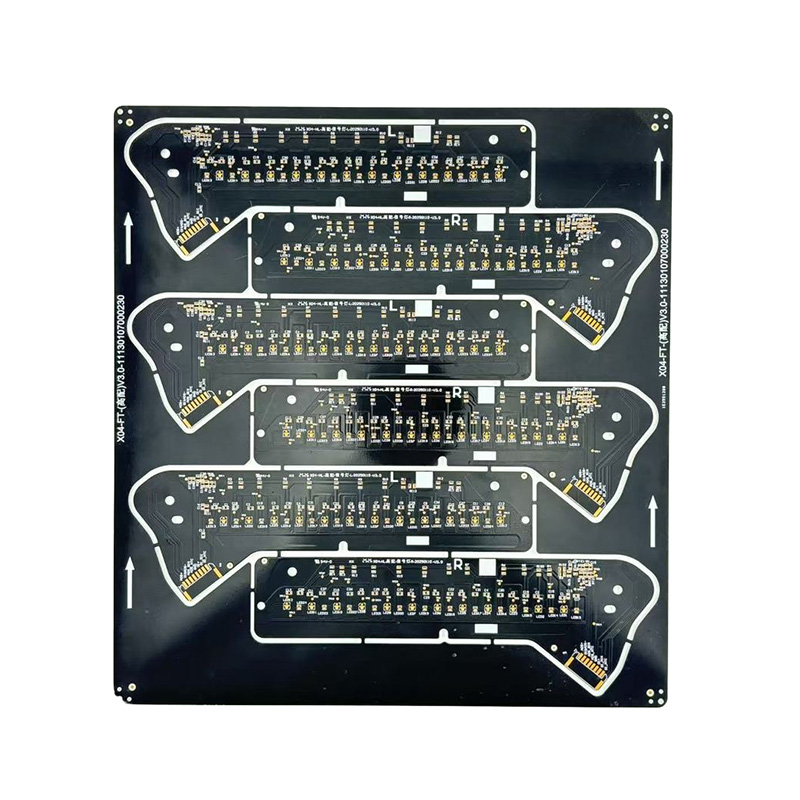
- LED lighting: High-brightness LED arrays for streetlighting, industrial high-bay, horticultural, and automotive headlamp applications are the largest single market for aluminum PCBs. The board simultaneously serves as LED carrier, circuit interconnect, and primary heat spreader to the luminaire housing.
- Power supplies and converters: Switch-mode power supply boards carrying MOSFETs, diodes, and inductors benefit from the aluminum base reducing component case-to-ambient thermal resistance without requiring a separate heatsink assembly.
- Automotive electronics: ECU power stages, LED driver modules, and battery management system boards in electric and hybrid vehicles use aluminum PCBs for their combination of thermal performance, vibration resistance, and compatibility with standard SMT assembly processes.
- Motor drives and inverters: Variable frequency drives and servo amplifiers mount gate driver circuits and power devices on aluminum PCBs that bolt directly to the drive chassis or heatsink extrusion.
Copper Core PCB: Maximum Thermal Conductivity in a Metal Core Construction
A copper core PCB replaces the aluminum base plate with a copper or copper alloy core, elevating the metal layer's thermal conductivity from ~160–200 W/m·K (aluminum) to approximately 385–400 W/m·K — roughly double the thermal conductivity of aluminum. This difference is most significant in applications with extreme localized power densities, where heat must be spread rapidly from a small source area before the thermal gradient drives junction temperature above the component's rated limit.
The performance advantage of copper core over aluminum core is most pronounced when:
- Power density exceeds approximately 15–20 W/cm² at a localized component footprint, where aluminum's lower lateral conductivity allows a hot spot to form before heat can spread to the board edges.
- The board-to-heatsink interface area is limited by packaging constraints, making lateral heat spreading within the board itself the primary means of distributing load across the interface.
- Coefficient of thermal expansion (CTE) matching is critical — copper's CTE (~17 ppm/°C) is closer to that of common semiconductor packages than aluminum's CTE (~23 ppm/°C), reducing thermo-mechanical stress at solder joints under repeated thermal cycling.
The primary trade-offs of copper core PCBs are cost and weight. Copper is approximately three times the material cost of aluminum per unit weight, and at 8.9 g/cm³ (versus 2.7 g/cm³ for aluminum), a copper core board of the same dimensions is roughly 3.3 times heavier. These factors restrict copper core PCBs to applications where thermal performance genuinely justifies the premium — high-power laser diode drivers, IGBT gate driver boards, radar transmitter modules, and precision power amplifiers are representative examples.
An important variant is the embedded copper coin PCB, in which a copper slug is press-fitted or plated into a localized region of an otherwise standard FR-4 or aluminum PCB directly beneath a high-power component. This approach delivers copper-level thermal performance precisely where it is needed, without converting the entire board to a copper core — significantly reducing cost and weight relative to a full copper core construction.
Ceramic PCB: The Premium Choice for Extreme Environments
A ceramic PCB departs entirely from the metal core construction and instead uses a monolithic ceramic substrate — most commonly aluminum oxide (Al₂O₃), aluminum nitride (AlN), or silicon nitride (Si₃N₄) — as both the mechanical base and the thermally conductive dielectric. Because the ceramic is intrinsically electrically insulating, no separate dielectric film is required between the substrate and the copper circuit layer. This eliminates the thermally resistive polymer interface that limits MCPCB performance and allows components to be mounted within microns of the ceramic surface.
The three principal ceramic substrate materials span a wide range of thermal performance and cost:
- Aluminum oxide (Al₂O₃, 96% and 99.6% purity): Thermal conductivity of 24–35 W/m·K. The most cost-effective ceramic substrate, widely used in thick-film hybrid circuits, sensor modules, and RF substrates. Mechanically strong and chemically inert, but its thermal conductivity is substantially lower than AlN — adequate for moderate power densities but insufficient for high-power applications where temperature rise must be minimized.
- Aluminum nitride (AlN): Thermal conductivity of 140–180 W/m·K — approaching that of aluminum metal — combined with a CTE of approximately 4.5 ppm/°C that closely matches silicon (2.6 ppm/°C) and GaAs (5.7 ppm/°C). AlN ceramic PCBs are the substrate of choice for power semiconductor modules, high-brightness LED flip-chip arrays, RF power amplifiers, and aerospace electronics operating at elevated temperatures. The CTE match to silicon virtually eliminates thermo-mechanical fatigue at die attach interfaces under thermal cycling, enabling long-term reliability in mission-critical applications.
- Silicon nitride (Si₃N₄): Thermal conductivity of 60–90 W/m·K combined with exceptional mechanical toughness (fracture toughness ~7 MPa·m½, versus ~3–4 MPa·m½ for AlN). Silicon nitride ceramic PCBs are specified where both high thermal conductivity and resistance to mechanical shock, vibration, and thermal shock are required simultaneously — electric vehicle power modules, railway traction inverters, and wind turbine converter boards are primary applications.
Copper circuitry is bonded to ceramic substrates by two primary processes: direct bonded copper (DBC), in which a copper foil is bonded to the ceramic surface by a controlled eutectic reaction at approximately 1065 °C, and active metal brazing (AMB), which uses a silver-copper-titanium braze alloy to bond copper to the ceramic at lower temperature with superior bond strength. DBC on AlN is the dominant technology for power module substrates; AMB is preferred for silicon nitride substrates and for applications requiring the highest thermal cycling reliability.
Performance Comparison Across All Four Substrate Types
| Parameter | Aluminum PCB | Copper Core PCB | Al₂O₃ Ceramic PCB | AlN Ceramic PCB |
|---|---|---|---|---|
| Core thermal conductivity | 160–205 W/m·K | 385–400 W/m·K | 24–35 W/m·K | 140–180 W/m·K |
| Dielectric layer required? | Yes | Yes | No | No |
| CTE (ppm/°C) | ~23 | ~17 | ~7 | ~4.5 |
| Max operating temperature | ~140 °C (dielectric limited) | ~140 °C (dielectric limited) | >350 °C | >350 °C |
| Relative material cost | Low | Medium-High | Medium | High |
| Machinability | Excellent | Good | Difficult (brittle) | Difficult (brittle) |
| Typical minimum feature size | 100 µm | 100 µm | 75–100 µm | 75–100 µm |
Application Mapping: Choosing the Right Substrate for Your Design
The decision tree for substrate selection starts with power density and operating temperature, then factors in mechanical environment, reliability target, and cost budget:
- Power density below 10 W/cm², operating temperature below 105 °C, cost-sensitive volume production: Standard aluminum PCB with a 1–3 W/m·K dielectric is the appropriate and most economical choice. LED lighting, consumer power supplies, and general-purpose motor controllers fall into this category.
- Power density 10–25 W/cm², thermal cycling requirements, moderate cost tolerance: Aluminum PCB with a high-performance 6–10 W/m·K ceramic-filled dielectric, or a copper core PCB where lateral spreading is the primary need. Automotive LED modules, DC-DC converter power stages, and industrial servo drives are representative.
- Power density above 25 W/cm², bare-die assembly, operating temperature above 150 °C: AlN ceramic PCB (DBC or AMB) is required. Power semiconductor modules for EV traction inverters, SiC and GaN device substrates, and high-power RF amplifiers for base stations and radar all demand AlN ceramic performance.
- High mechanical shock and vibration combined with elevated power density: Silicon nitride ceramic PCB delivers the unique combination of high thermal conductivity and fracture toughness needed for railway traction, aerospace, and heavy industrial inverter applications.
- RF and microwave circuits requiring controlled dielectric constant and low loss tangent: Al₂O₃ ceramic PCB provides the stable, low-loss dielectric environment required for microwave hybrid circuits, phased array antenna elements, and precision oscillator substrates where polymer-based boards exhibit unacceptable dielectric variation with temperature and humidity.
Manufacturing and Design Considerations
Each substrate type imposes specific design rules and manufacturing constraints that must be understood before committing to a substrate choice:
- Aluminum and copper core PCBs are processed through standard SMT assembly lines with minor modifications — solder paste printing, pick-and-place, and reflow soldering proceed as for FR-4 boards. The metal base requires drilling with carbide tooling rather than standard PCB drill bits, and boards must be routed or punched rather than scored and broken. Edge connector areas and mounting hole surrounds require careful design to maintain electrical isolation from the metal core.
- Ceramic PCBs are inherently brittle and cannot be drilled, punched, or routed by standard PCB tooling without fracture. Holes and board outlines must be laser-cut or machined by diamond-tipped tools before sintering, or cut by ultrafast laser (picosecond or femtosecond) after copper bonding. This constraint limits ceramic PCB panel utilization and increases per-piece cost significantly compared to MCPCB. Handling and assembly require fixtures that avoid point loads and edge impacts.
- Thermal simulation is strongly recommended before finalizing substrate selection. CFD or finite-element thermal models that accurately represent the dielectric layer thermal resistance (for MCPCBs) or the ceramic substrate conductivity (for ceramic PCBs) allow the designer to verify that the chosen substrate keeps all component junction temperatures within rated limits at maximum power dissipation — before prototype tooling is committed.
- Surface finish selection affects both solderability and wire bond compatibility. HASL, ENIG, and OSP finishes are available on aluminum and copper core PCBs. DBC AlN substrates for bare-die assembly are typically supplied with a nickel-gold finish over the copper circuit layer, compatible with both eutectic solder die attach and gold or aluminum wire bonding.
Whether the design calls for a cost-optimized aluminum PCB, a high-spreading-performance copper core PCB, or the extreme thermal and environmental capability of an AlN ceramic PCB, the common thread across all metal core PCB and ceramic substrate technologies is a systematic engineering approach: quantify the thermal requirement first, then select the substrate whose performance, processability, and cost profile best serves that requirement across the full product lifecycle.
Recommended Products


 LET'S CREATE THE FUTURE TOGETHER

Contact Us Anytime
Copyright © Anhui Hongxin Electronic Technology Co., Ltd. All Rights
Reserved.
privacy
Wholesale Printed Circuit Board Suppliers, Manufacturers
![]()
