


 English
  Español
  Français
Flexible PCB Board Guide: Materials, Bend Radius Rules and Applications
A backup camera cable that twists with every turn of the steering wheel, a hearing aid smaller than a fingertip, a foldable display rated for 200,000 open-and-close cycles: none of these can be wired with a flat FR4 board and a row of connectors. A flexible PCB board - also called a flex circuit or FPC - replaces the rigid glass-epoxy core with thin polyimide film, so copper traces can bend, fold, and twist while signals keep flowing through the moving part. The practical conclusion comes first: flex is worth its premium exactly when the circuit has to move, fold, or live inside a curved housing; if a board sits flat for its whole service life, rigid FR4 is still cheaper and usually the better choice. What follows covers what flex boards are made of, how they compare with rigid construction on real numbers, the bend radius rules that keep traces alive, and what to check before releasing an order.
Content
What a Flexible PCB Board Is Actually Made Of
The short answer is a deliberately thin stack: polyimide film, rolled-annealed copper, and a flexible coverlay, with finished thickness usually between 0.05 mm and 0.3 mm - roughly one tenth of a standard 1.6 mm rigid board. Each layer is selected for bending performance rather than rigidity.
- Base film: polyimide (PI), commonly 12.5 µm, 25 µm, or 50 µm thick. PI holds its mechanical properties from cryogenic temperatures to well beyond soldering heat - material suppliers commonly quote usable exposure from about -200 °C to 400 °C.
- Copper: rolled-annealed (RA) foil instead of electrodeposited foil. Its grain structure stretches with the film instead of fracturing, which is what makes hundreds of thousands of bend cycles possible.
- Coverlay: PI film with punched pad openings laminated over the copper. It replaces solder mask, which is too brittle to flex, and its alignment tolerance must be budgeted into pad design.
- Stiffeners: local FR4, PI, or stainless pieces bonded where connectors and components sit, keeping the bendable region clean.
- Adhesiveless laminate: copper cast directly onto PI. It costs slightly more but handles heat and repeated flexing better - a worthwhile upgrade for dynamic duty.
Flex vs Rigid: Where the Price Gap Closes
Per square meter of raw material, flex always loses to FR4. System-level accounting usually tells the opposite story, because one flex circuit can replace two connectors, a ribbon cable, and their solder joints - each one a purchased part, an assembly step, and a failure point that simply disappears. Add the thickness and weight savings and the comparison looks like this:
| Attribute | Flexible PCB (polyimide) | Rigid PCB (FR4) |
|---|---|---|
| Base material | PI film, typically 12.5-50 µm | Woven glass-epoxy, 0.2-2.0 mm |
| Typical finished thickness | 0.05-0.3 mm | 0.4-2.4 mm |
| Weight per unit area | Roughly 10-20 times lighter than 1.6 mm FR4 | Reference point |
| Bending | Static folds and dynamic cycling | None; requires connectors or cable |
| Temperature endurance | PI film tolerates roughly -200 °C to 400 °C exposure | Limited by FR4 Tg, typically 130-180 °C |
| Relative cost | Higher material cost, lower system cost | Lower material cost, more interconnects |
| Best fit | Moving, folding, curved, weight-critical assemblies | Flat, static, cost-driven volumes |
Where the assembly never moves, rigid single-, double-, and multilayer boards remain the default cost baseline, and the choice between them is mostly layer count and surface finish rather than materials.
The Four Flex Constructions You Will Be Quoted
Suppliers quote four standard constructions, and the motion profile of your assembly decides which one is right.
Single-Sided Flex
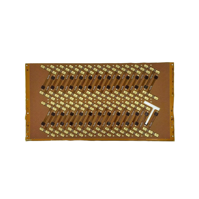
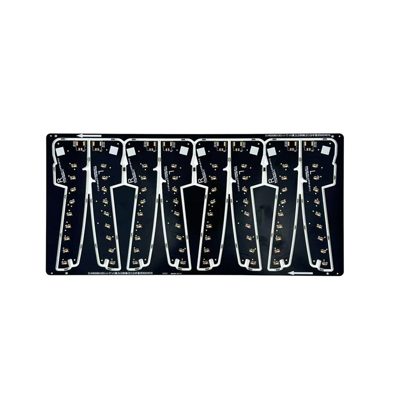
One copper layer on polyimide with coverlay on top. It is the cheapest option and, counterintuitively, the most durable under repeated bending, because all of the copper sits near the neutral axis where bending stress approaches zero. Print heads, antenna feeders, LED strips, and long dynamic links are its home territory.
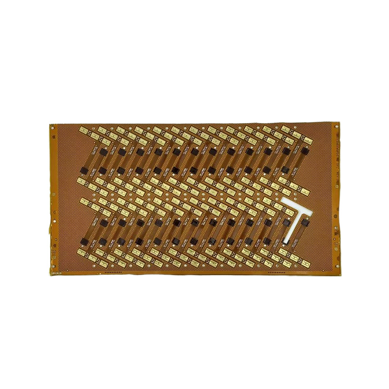 High-Flex Flexible PCBA single-copper-layer polyimide flex PCB suited to repeated bending, such as print heads, antenna feeders, and LED strips. Its construction places copper near the neutral axis, offering strong durability at low cost.View Product →
Double-Sided Flex
Two copper layers joined by plated through-holes, with coverlay on both faces. Routing freedom improves sharply, which suits boards that fold once during installation and then hold still: instrument clusters, camera modules, wrapped sensor housings. It is the wrong pick for continuous cycling.
Multilayer Flex
Three or more PI and copper layers bonded into one flex stack. This is where impedance-controlled pairs and dense routing live, and it is also where bend capability falls fastest: every added layer pushes copper away from the neutral axis and increases total thickness.
Rigid-Flex
Rigid FR4 sections laminated to flexible PI layers as one continuous board. Connectors between rigid blocks disappear, assembly collapses to a single part, and the solder joints that used to fail in vibration stop existing. Fabrication costs more; assembled cost and field reliability usually come out ahead, which is why rigid-flex is standard in aerospace, medical devices, and high-end automotive modules.
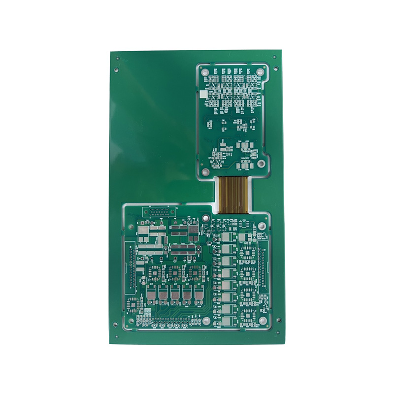 High-Reliability Rigid-Flex PCBRigid FR4 sections laminated with flexible polyimide layers form one continuous board, eliminating connectors and weak solder joints. Ideal for aerospace, medical, and automotive modules needing static support plus controlled flexing.View Product →
Bend Radius Rules That Decide Field Reliability
Cracked copper at the fold is the most common flex failure seen in the field, and in most cases the bend radius was specified too tight for the construction. Two distinctions matter before any number goes on the drawing: static versus dynamic duty, and construction type.
| Flex construction | Static minimum bend radius | Dynamic minimum bend radius |
|---|---|---|
| Single-sided | 6t | 100t |
| Double-sided | 10-12t | 150t |
| Multilayer and rigid-flex | 20t or more | Not recommended for dynamic duty |
Applied in practice: a 0.15 mm double-sided flex folded once during installation needs a radius of roughly 1.8 mm or more, while a strap built to flex millions of times is typically made on 12.5 µm PI with 9-12 µm copper so the 100t radius fits inside the product's mechanical envelope. Layout discipline inside the bend zone matters as much as the radius itself:
- Route conductors perpendicular to the bend line so stress spreads along the trace instead of concentrating at an angle.
- Keep vias and plated through-holes out of bend zones; drilled holes are crack initiation points.
- Add teardrops where traces narrow into pads, and avoid abrupt width changes inside the bend.
- Use hatched ground planes instead of solid copper pours in bend regions.
- Balance copper symmetrically about the neutral axis on multilayer stacks, and stagger pads so no single path carries all the stress.
Where Flexible PCB Boards Earn Their Place
The same physical properties recur across very different industries:
- Consumer electronics: camera modules, foldable hinge cabling, and thin displays, where every 0.1 mm of stack height is contested.
- Automotive: steering wheel switches, instrument clusters, sensor links, and lighting assemblies, where vibration destroys rigid interconnects and IATF16949-certified supply is mandatory.
- Medical: hearing aids, oxygen concentrators, and wearable patches, where small curved shells leave no room for connectors.
- Industrial and robotics: moving joints, print mechanisms, and motion control, where a flex circuit survives cycle counts that would fatigue a cable harness.
Automotive lighting is a representative case: LED modules follow curved housings, tolerate high temperatures, and must pass the same qualification regime as any safety-relevant component, so fabricating the bare flex and assembling the finished board inside one certified quality system removes a predictable source of coordination failure.
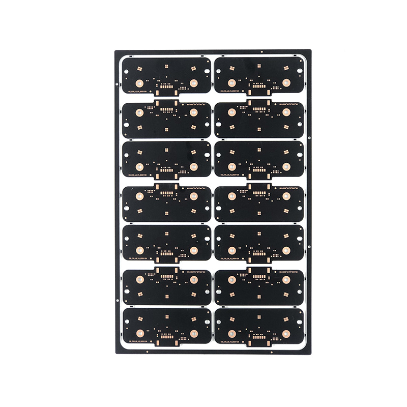
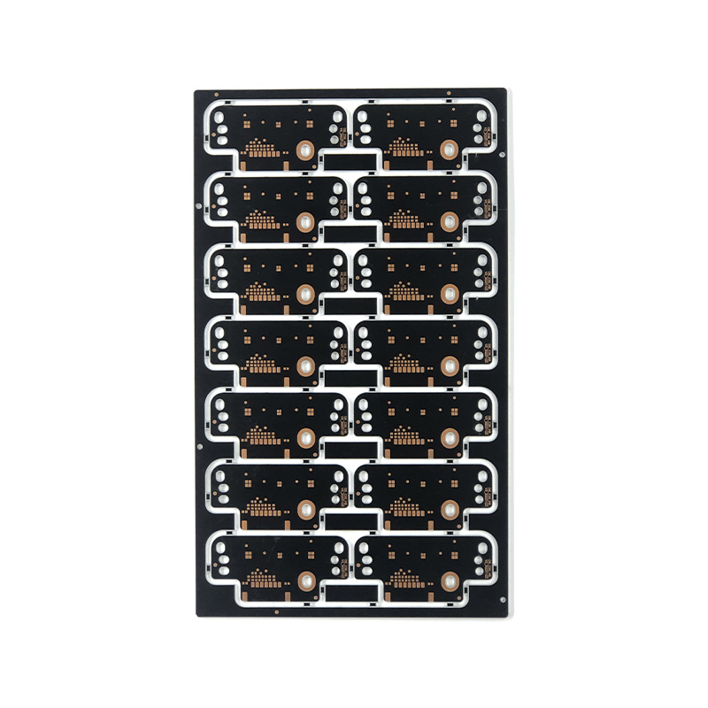
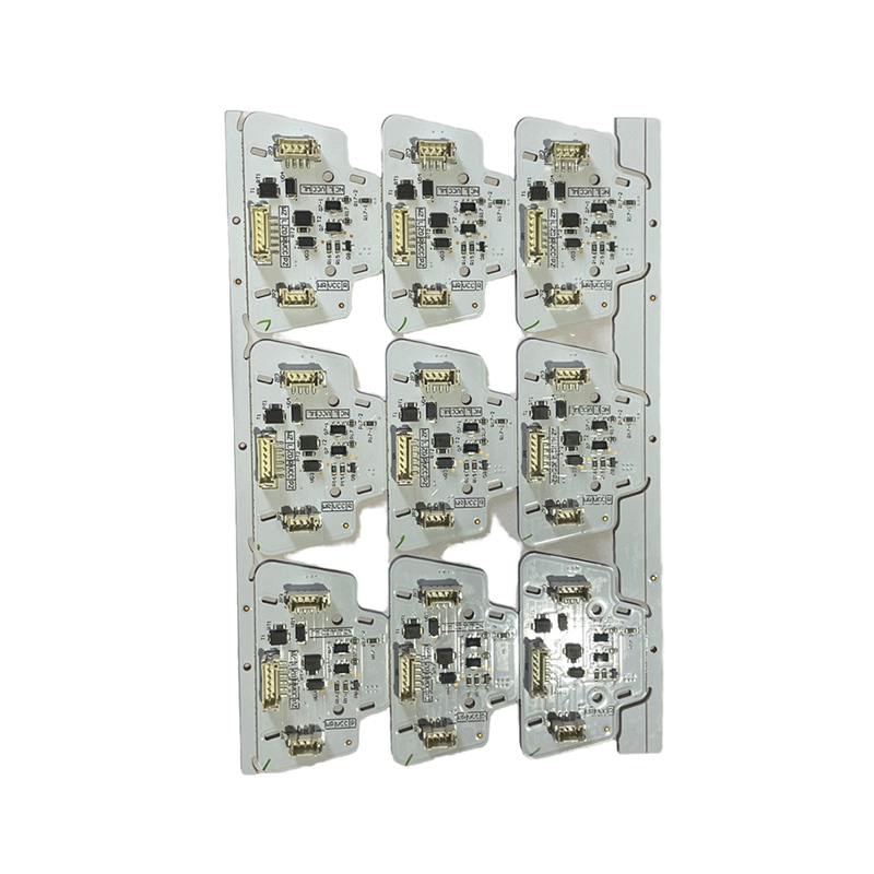 Automotive Lighting PCBABuilt on FR4 or aluminum substrates for high-temperature, waterproof operation, this PCBA supports LED driving and adaptive lighting functions. Bare flex fabrication and assembly under one certified quality system reduce coordination failures.View Product →
A Sourcing Checklist Before You Release the Order
Certifications and test data predict field performance better than unit price does. Work through this list before committing to a fabricator:
- Confirm certifications matched to your market: ISO9001 as the baseline, IATF16949 for automotive programs, UL recognition for the material system.
- Define the acceptance class explicitly - Class 2 or Class 3 per IPC-6013 and IPC-2223 - on the drawing instead of leaving it to quotation defaults.
- Ask for bend-cycle test data for the specific construction and copper weight, not a general flexibility claim.
- Pin down coverlay alignment tolerance, stiffener placement, and impedance values in the fabrication notes.
- Compare total cost: flex board plus assembly versus rigid board plus connectors plus cable plus extra solder joints.
- Check prototype-to-volume continuity: sampling turnaround, batch lead times, and whether the same process window carries from first article to mass production.
That last point is where launch schedules are won or lost. Manufacturers that publish their service and delivery commitments - sampling speed, batch lead times by layer count, and quality system documents - let you plan a program around a schedule instead of guesswork, and fabricating bare flex boards and assembling finished PCBA under one roof removes an entire coordination layer.
Match the construction to the motion profile, design the bend zones before routing a single trace, and buy from a supplier who can show cycle test data and the certifications your market requires. Do those three things and a flexible PCB board stops being a specialty product and becomes what it actually is: the most reliable way to carry a signal through a part that moves.

 LET'S CREATE THE FUTURE TOGETHER

Contact Us Anytime
Copyright © Anhui Hongxin Electronic Technology Co., Ltd. All Rights
Reserved.
privacy
Wholesale Printed Circuit Board Suppliers, Manufacturers

