


 English
 Español
 Français

What Are Circuit Boards Made Of? A PCB Maker's Guide to Board Materials
Ask most engineers what a circuit board is made of and you will get a single word back: fiberglass. That answer is correct, but it covers only the first layer of a longer story. A printed circuit board is a carefully engineered stack of materials, and every one of them has to earn its place. The substrate gives the board its body and its electrical insulation, the copper carries the current, the solder mask protects the surface, and the final finish keeps the copper solderable for years.
We have been fabricating boards at our Guangde facility since 2013, from simple single-sided panels up to 32-layer stacks, so we tend to answer this question the way a fabricator does. The real question is not what a PCB is made of in general, but which combination of materials will survive your product's environment for its expected lifetime.
Content
- 1 The Core Ingredients of a Circuit Board
- 2 The Substrate: Glass Cloth, Resin, and the Alternatives
- 3 Copper: The Part That Carries the Current
- 4 When Fiberglass Is the Wrong Choice
- 5 Solder Mask, Silkscreen, and Surface Finishes
- 6 Circuit Board Materials at a Glance
- 7 How the Application Picks the Material
- 8 Practical Notes from the Shop Floor
The Core Ingredients of a Circuit Board
Strip away the jargon and almost every board is built from the same short list of materials:
- Substrate: the insulating base, usually woven fiberglass bonded with epoxy resin.
- Copper foil: laminated onto the substrate and etched into traces, pads, and planes.
- Plating: copper, and sometimes tin or gold, deposited inside drilled holes to link the layers.
- Solder mask: the colored coating that covers everything except the pads you need to solder.
- Silkscreen: the printed legend that identifies components and reference designators.
- Surface finish: a thin metallic or organic layer that stops exposed copper from oxidizing.
Each of these materials can be swapped, upgraded, or thickened, and every substitution changes cost, manufacturability, and field reliability at the same time.
The Substrate: Glass Cloth, Resin, and the Alternatives
Standard FR-4 begins with woven glass cloth. The cloth is impregnated with epoxy resin and partially cured into a sheet called prepreg, then stacked and pressed under heat and pressure until the resin flows and hardens. The result is rigid, dimensionally stable, and an excellent insulator: the glass supplies mechanical strength while the resin defines the electrical and thermal behavior.
From that starting point the family branches quickly:
- FR-4 in standard, high-Tg, and halogen-free grades, the workhorse of the industry.
- CEM-1 and CEM-3, composite epoxies with a non-woven glass core for cost-sensitive products.
- FR-1 and FR-2, paper-based laminates used in very low-cost single-sided boards.
- Polyimide film, the flexible base for FPC and rigid-flex designs that need to bend.
- PTFE and ceramic-filled hydrocarbon laminates, chosen when signal loss must stay low at gigahertz frequencies.
Most of the important trade-offs live in the resin system rather than the copper. Glass transition temperature, decomposition temperature, dielectric constant, and moisture absorption all come from the laminate chemistry.
 Double-Sided OSP PCBFR4 PCBs utilize an epoxy resin fiberglass substrate, offering excellent mechanical strength, high-temperature resistance, and electrical insulation properties. They a...View Product →
A double-sided FR-4 board with an OSP finish is the everyday example: standard laminate, standard thickness, and a finish that suits high-volume reflow soldering without adding cost.
Copper: The Part That Carries the Current
Copper is the second essential ingredient. Foil is specified by weight, and the conversion is worth memorizing: one ounce of copper spread over one square foot is roughly 35 microns thick. Fine-pitch digital designs usually run on half-ounce or one-ounce foil, power boards step up to two ounces, and heavy-copper work goes to three ounces and beyond.
Copper appears in more places than the visible traces. During fabrication, additional copper is electroplated into every drilled hole to form a continuous barrel wall, and the outer layers are pattern-plated before etching. The quality of that plating, not just its thickness, decides whether a via survives repeated thermal cycling.
When current demands rise, the answer is often more copper rather than more board area. Heavy-copper constructions spread the load across inner layers, which keeps temperature rise under control without an external heat sink.
 14-Layer CopperThick Copper PCBs utilize ultra-thick copper foil ranging from 3oz to 20oz, boasting exceptional current-carrying capacity (over 100A) and high-temperature resistance ...View Product →
When Fiberglass Is the Wrong Choice
FR-4 answers most questions, but three material families take over when it cannot.
Metal-core and copper-core boards
Aluminum is used as the base when heat has to leave the board quickly. A thin dielectric layer is bonded to the aluminum, copper circuitry is etched on top, and the metal backing acts as a heat spreader. Copper-core versions go further, carrying very high current densities in LED lighting, motor drives, and power conversion. Thin as it is, that dielectric layer still has to hold off the full working voltage, so its thickness and thermal conductivity are the two numbers worth checking first.
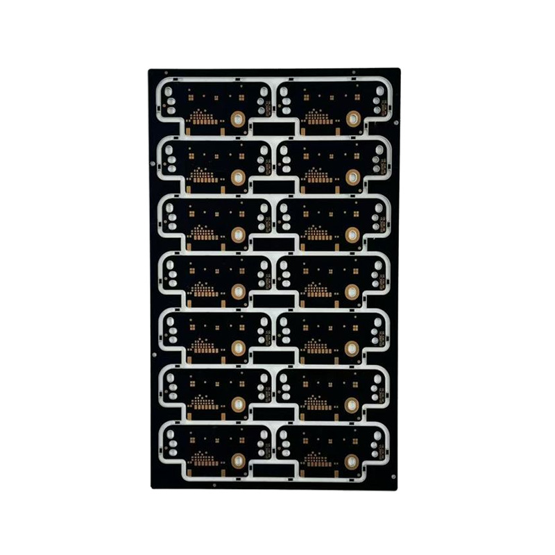 Single-Sided Aluminum PCBMetal substrates utilize aluminum, copper, and other metals as their core thermally conductive layer. A specialized insulating dielectric achieves superior heat dissip...View Product →
Ceramic substrates
Alumina and aluminum nitride bring thermal conductivity that no polymer laminate can match, along with a coefficient of thermal expansion close to silicon. They appear in high-power LED modules, RF power stages, and sensors that must keep working through wide temperature swings.
Flexible films
Polyimide replaces glass cloth when the board has to bend. The same copper and finish rules apply, only the base changes, and with it the handling rules during assembly.
Solder Mask, Silkscreen, and Surface Finishes
Solder mask is an epoxy-based coating applied over the board and then cured. It stops solder from bridging between pads, shields the copper underneath from moisture and contamination, and gives the board its familiar color. Green is traditional because it has the longest track record in imaging and inspection, but black, blue, red, and matte black are routine today. Silkscreen ink is printed on top of the mask to mark component references and polarity, and while it carries no current, it is the first thing an assembly operator relies on.
The surface finish is the last material decision and one of the most consequential. Hot air solder leveling is the low-cost option, OSP is organic and fades after a few reflows, and ENIG or immersion silver provides a flat surface for fine-pitch parts. Where a board is inserted and removed repeatedly, hard gold is the answer. All of our finishes are available in lead-free versions.
Circuit Board Materials at a Glance
The table below summarizes the material systems we build most often and what each one is made of.
| Material System | What It Is Made Of | Typical Use |
|---|---|---|
| FR-4 | Woven fiberglass cloth bonded with epoxy resin | General electronics, 1 to 32 layers |
| CEM-3 | Non-woven glass core with epoxy resin | Cost-sensitive consumer boards |
| Aluminum metal-core | Aluminum base, dielectric layer, copper foil | LED lighting and power supplies |
| Copper-core | Thick copper base with dielectric and copper foil | High-current power circuits |
| Alumina ceramic | Sintered aluminum oxide with thick-film copper | RF power, sensors, LED modules |
| Polyimide flexible | Polyimide film with rolled or electrodeposited copper | Flexible and rigid-flex assemblies |
| High-frequency laminate | PTFE or ceramic-filled hydrocarbon | Radar, 5G, microwave links |
How the Application Picks the Material
Material selection is rarely a free choice. It follows the environment the board will live in.
Consumer and appliance products
Where cost dominates, standard FR-4 or CEM-3 with a HASL or OSP finish is usually enough.
Automotive and industrial control
Vibration, thermal cycling, and long service life push designs toward high-Tg laminates, thicker copper, and finishes such as ENIG that survive repeated reflow.
Power and high-frequency designs
Thermal management and signal integrity take priority, which means metal-core, ceramic, or PTFE-based materials rather than a thicker glass board.
If you are unsure where your product sits, it helps to see how similar boards are already being built. You can browse the application areas we support to see the material combinations already proven in each segment.
Practical Notes from the Shop Floor
A few things we tell customers who are choosing materials for the first time:
- Pick the finish before the layout is frozen, because pad geometry and via tenting depend on it.
- Match copper weight to current, not to habit, since oversized copper increases etch difficulty and cost.
- Ask about Tg early, because a high-Tg laminate costs a little more and removes a whole class of field failures.
- Confirm the stack-up drawing before release, because most delays start as a missing or ambiguous layer.
If you want a deeper look at how laminate choice, copper weight, and finish interact, our guide to selecting FR-4, RF, and metal-core materials walks through the comparisons in more detail.
So what are circuit boards made of? Glass cloth and epoxy resin, copper foil and plated barrels, a solder mask, a printed legend, and a final finish that keeps it all solderable. The interesting part is not the list itself but the way those materials are matched to the job. Get that match right and the board quietly does its work for a decade or more.
Recommended Products
-
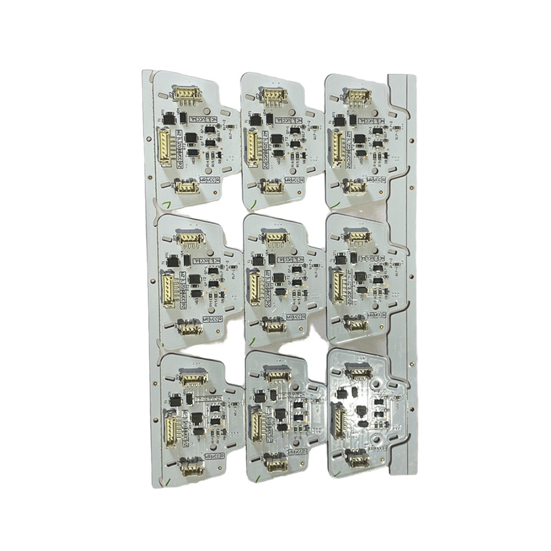

Automotive Lighting PCBA
-
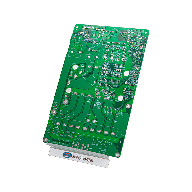
Double-Sided Green Lead-Free Soldered PCB For Power & Automotive Electronics
-
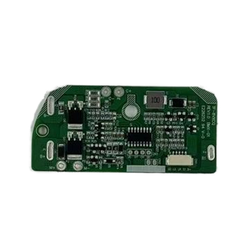
Remote Control Consumer PCBA
-
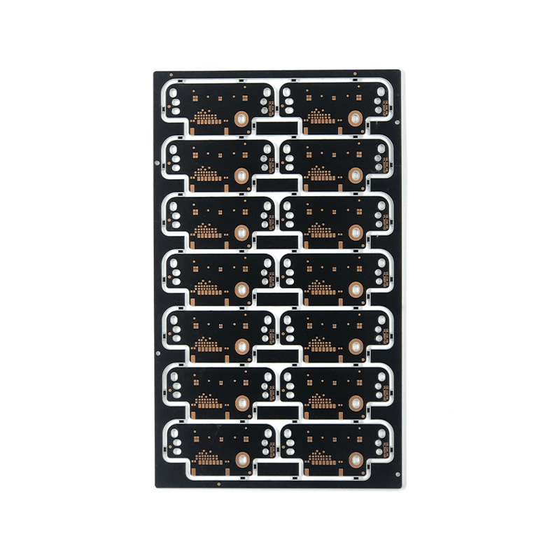
Double-Sided Black High Precision OSP PCB Board
-
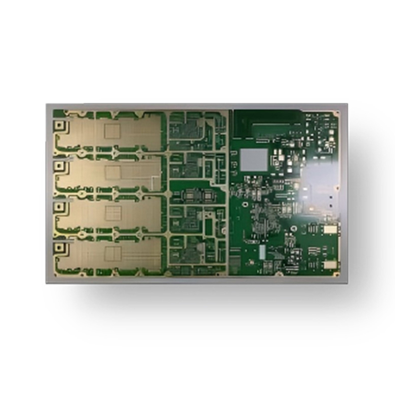
10-Layer Embedded Copper-Based Amplifier Board
-
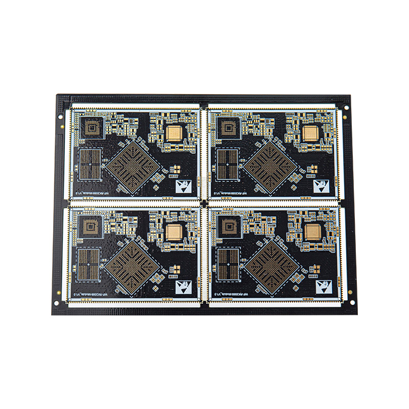
6-Layer Gold-Plated Board, Line Width And Spacing Of 3/3, BGA, Half-Hole Technology
 LET'S CREATE THE FUTURE TOGETHER

Contact Us Anytime
Copyright © Anhui Hongxin Electronic Technology Co., Ltd. All Rights
Reserved.
privacy
Wholesale Printed Circuit Board Suppliers, Manufacturers

